St. Louis, Missouri

Space Elevators Incorporated

Physical Parts → Editable CAD → Validated Production

Reverse engineering, metrology & product development.

The business

We turn physical objects into editable CAD, and CAD into parts that fit.

Space Elevators Incorporated is a small engineering practice in St. Louis, Missouri. We measure existing parts, rebuild them as clean parametric models, check the models against the originals, and carry them through to prototypes and production-ready drawings.

Most of our work begins with an object someone hands us: a discontinued component, a worn casting, a fixture with no drawing, a part whose documentation was lost decades ago. We are equally interested in the other direction, taking a rough idea to a part that can be made, measured, and made again.

Reverse engineering

Existing parts captured and reconstructed as native, feature-based CAD you can edit, not a mesh wrapped in a STEP file.

  • Machined, cast, molded, and sheet-metal parts
  • Assemblies and mating interfaces
  • Design-intent recovery and tolerance inference

Metrology & inspection

Measurement chosen to match the question: 3D scanning for form, probing and gauges for the dimensions that matter.

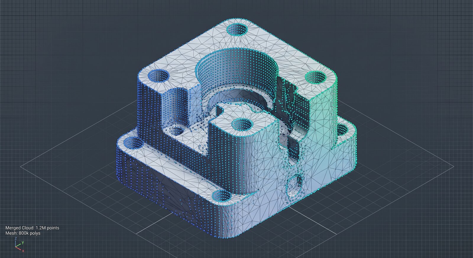
  • 3D scanning and point-cloud processing
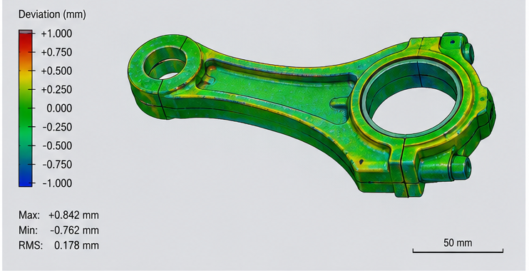
  • Model-to-scan deviation analysis
  • Inspection reports and as-built documentation

Prototyping & production support

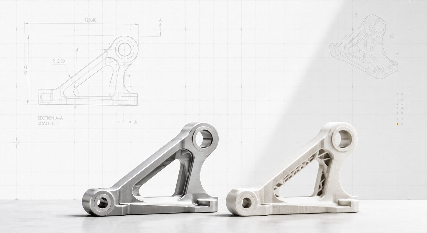
From model to object: printed and machined prototypes, fit checks, drawings with GD&T, and process selection with your shop or ours.

  • Rapid prototypes for fit and function
  • Manufacturing drawings and revision control
  • Small-batch coordination with partner shops
Method

Capture. Understand. Reconstruct. Validate. Manufacture.

  1. 01

    Capture

    3D scanning for surfaces, probing and hand gauges for critical features, photographs and notes for everything else.

    Output point cloud, reference measurements, photo record

  2. 02

    Understand

    Which surfaces are functional and which are cosmetic. What was machined and what was cast. What the part mates to and what tolerances it actually needs.

    Output feature map, datum scheme, tolerance plan

  3. 03

    Reconstruct

    The part is rebuilt as a parametric model with a real feature tree, in the CAD system you already use. Dimensions are rationalized to design intent, not copied from a worn sample.

    Output native CAD, STEP, feature tree

  4. 04

    Validate

    The model is compared to the scan with a color-mapped deviation analysis, then to the real world with a fit check on a printed or machined prototype.

    Output deviation report, fit-check record, revisions

  5. 05

    Manufacture

    Drawings with GD&T, process and material recommendations, and coordination with your shop or a partner until parts arrive and fit.

    Output drawing package, first articles, inspection

Problems

Bring us the odd ones.

Work

Evidence, not adjectives.

Project write-ups are being documented. The entries below show the format with placeholder imagery: a real part, a real scan, a real model, and the measured difference between them.

Begin

Send us the part.

Describe the object, what you need to do with it, and roughly how many you need. Photographs help, even bad ones. We will reply with questions, a rough scope, and a price.

St. Louis, Missouri
Parts by mail, courier, or drop-off

  1. 01Tell us what the part is and what it mates to.
  2. 02Send photographs, any drawings, and the part itself.
  3. 03We scope the work and quote a fixed price where we can.
  4. 04You receive native CAD, a deviation report, and drawings.